Metrological X-ray computed tomography (XCT): Micro-technology use cases
X-ray computed tomography (XCT) is increasingly used to dimensionally characterise workpieces. Here, we present micro-technology use cases to demonstrate the achievable accuracy and limitations of XCT. This is important, since task-specific measurement uncertainties can deviate greatly from machine specifications, which usually rely on measurements of highly accurate multi-sphere standards that cause little image artefacts (use case 1). Actual workpieces (use cases 2 - 4) usually suffer from influences depending on their material and geometry. These include XCT specific artefacts, such as beam hardening, scatter and phase contrast, as well as surface quality and form deviations of the workpieces.
For the use cases, simulation-assisted approaches were used to estimate task-specific measurement uncertainties. The values measured by XCT were compared to highly accurate reference calibrations on a tactile coordinate measuring machine (µCMM) [1].
Metrology XCT system METAS-CT
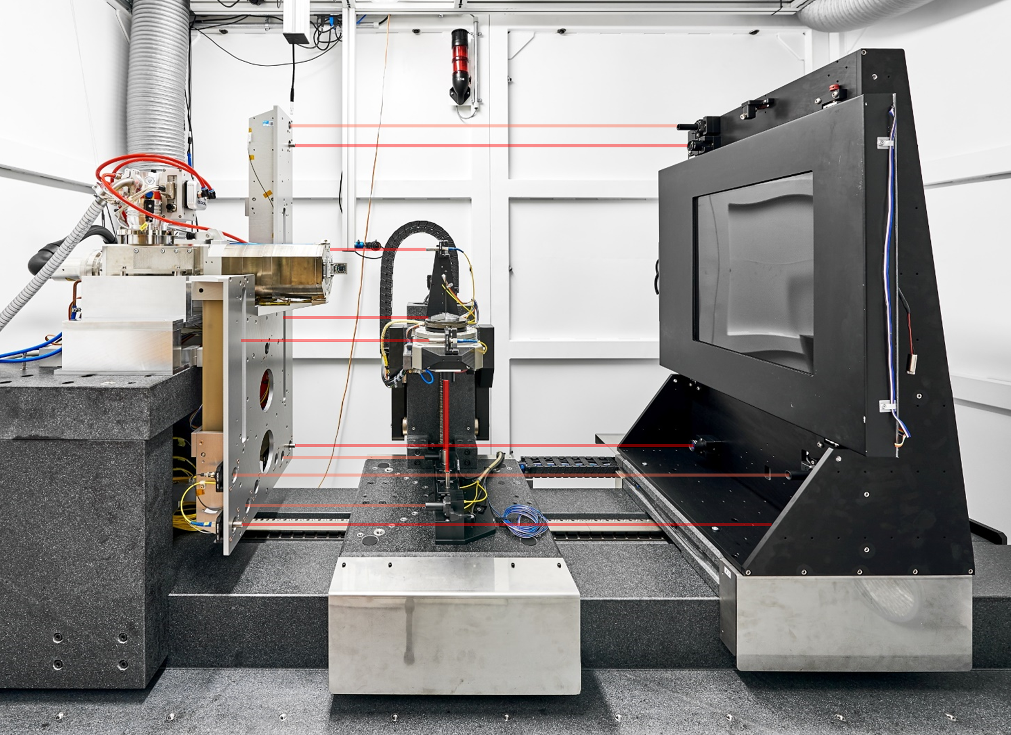
The metrology XCT system METAS-CT is comprehensively characterised [2,3] and equipped with an interferometric metrology system to account for machine geometry deviations [4,5]. A sub-microfocus X-ray tube with 190 kV acceleration voltage enables resolutions down to below 1 µm. In XCT, scan times roughly scale with the number of voxels (volume elements), i.e. doubling the resolution extends measurement times eightfold. At resolutions close to 1 µm, this usually results in scan times of several hours. The X-ray energy limits maximal transmission thicknesses to about 10 mm for steel, 65 mm for aluminium, 80 mm for glass and 150 mm for plastics. For all use cases, voxel sizes were in the order of 2 µm.
Use case 1: Small multi-sphere standard
- Function: Performance verification of XCT systems
- Material: Ruby (spheres) and quartz (base)
- Outer dimensions: 4 x 4 x 2 mm3
- Measurands: Sphere-to-sphere centre distances
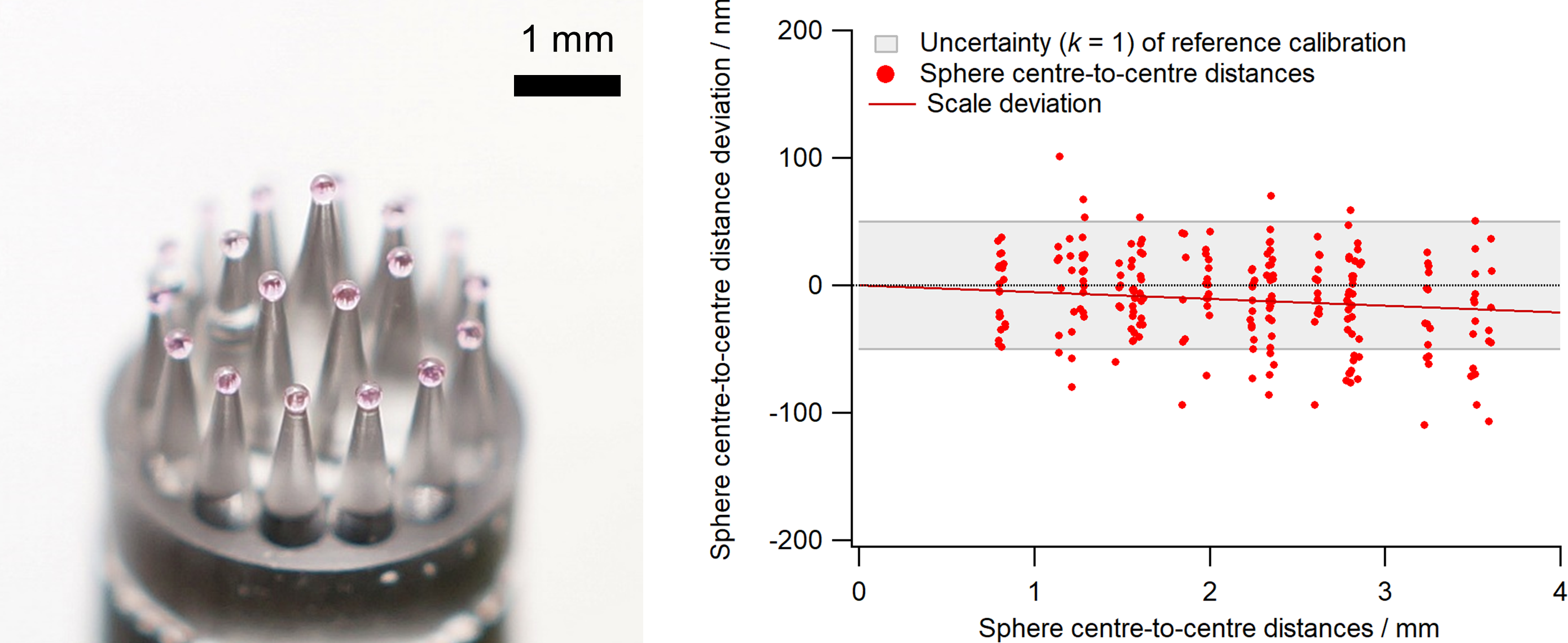
Small multi-sphere standard (Zeiss METROTOM-Check nano) and corresponding sphere centre-to-centre distance deviations between an XCT measurement and a tactile reference calibration (scale deviation -5∙10-6, standard deviation 35 nm).
Use case 2: Watch test part
- Function: Test part evaluate selective laser etching (SLE) manufacturing technology (kindly provided by the Association Suisse pour la Recherche Horlogère, ASRH)
- Material: BK7 glass
- Outer dimensions: 15 x 6.6 x 0.2 mm3
- Measurement uncertainty estimation: hybrid [4]
- Measurands: Diameters and size
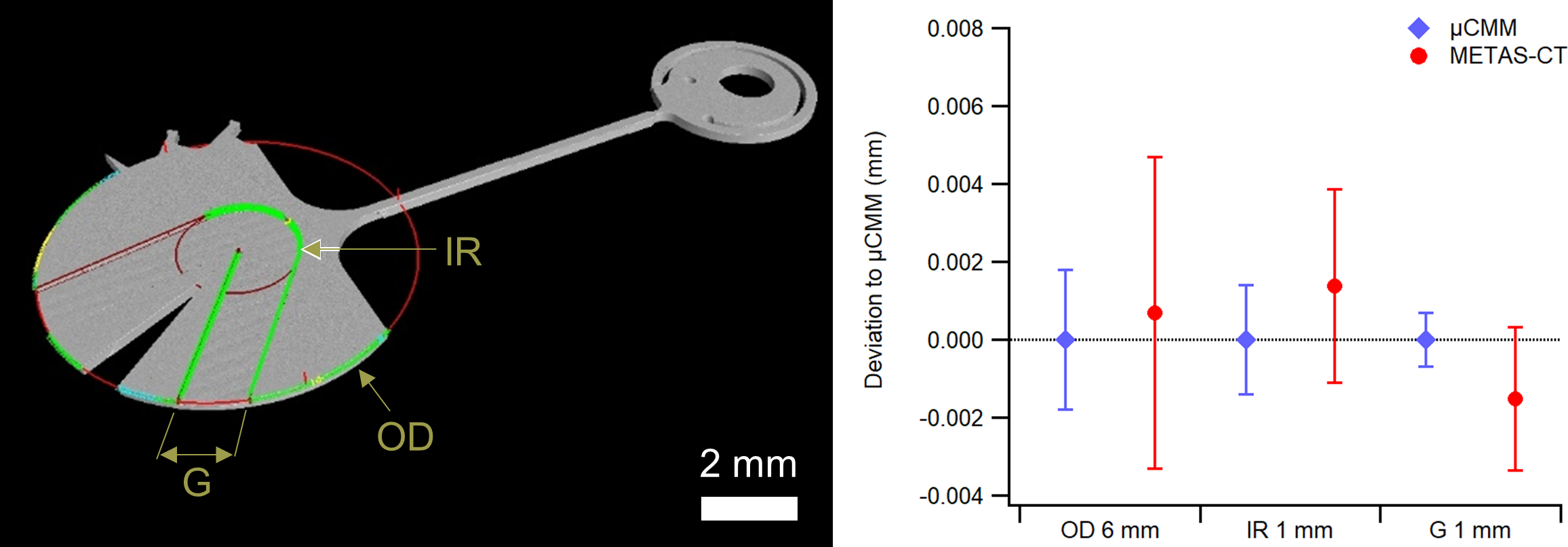
XCT reconstruction of the SLE watch test part and comparison of the outer diameter (OD), the inner radius (IR), and the groove width (G) to tactile reference measurements (µCMM). The uncertainties for both µCMM and XCT were dominated by the surface quality and form deviations of the workpiece.
Use case 3: Glass fibre ferrule
- Function: Multi-fibre push-on connector (MPO)
- Material: High-performance thermoplastic
- Outer dimensions: 8 x 7 x 2.5 mm3
- Measurement uncertainty estimation: Virtual XCT (Monte-Carlo) [6]
- Measurands: Hole positions, diameters and roundness deviations
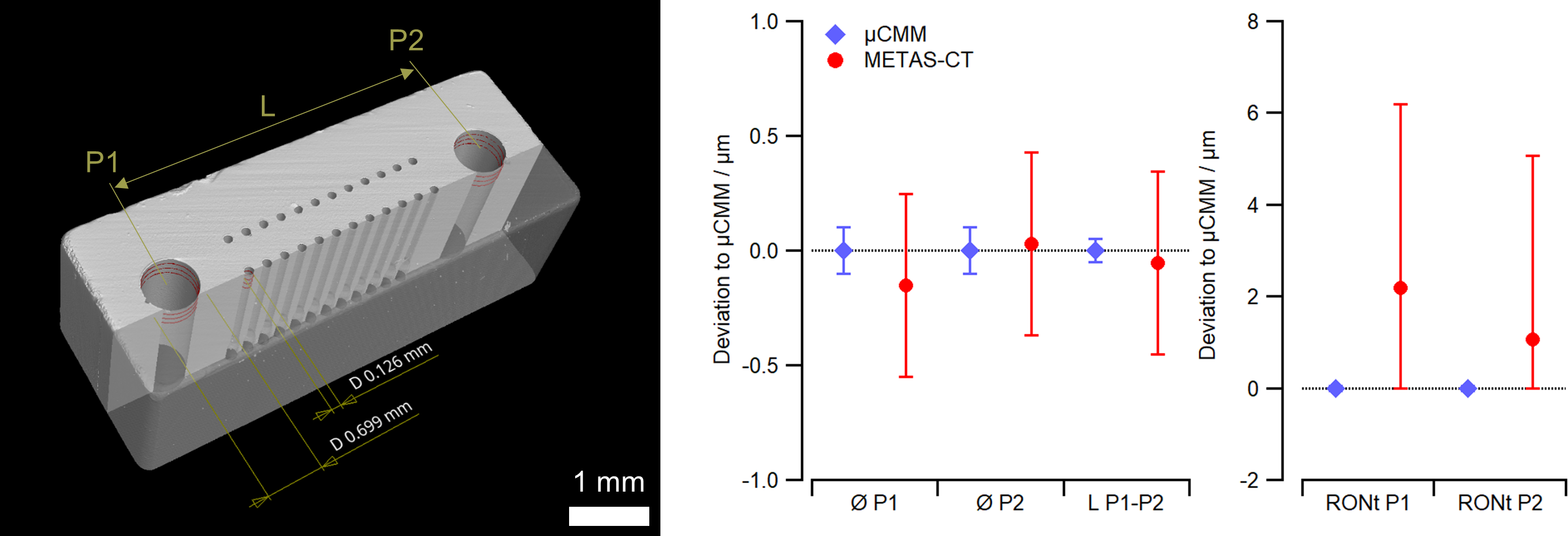
XCT reconstruction of the glass fibre ferrule with 24 fibre holes (Ø 0.126 µm) and two guide pin holes (P; Ø 0.7 mm). Measurement uncertainties were estimated using a virtual XCT (Monte-Carlo simulations). All measured values were compatible with tactile reference calibrations (µCMM) and the task specific uncertainties were 0.4 µm for guide pin hole diameters (Ø) and distance (L), 4 µm for roundness deviation (RONt) and 0.6 µm for fibre hole diameters (not shown). The measurement uncertainty of RONt was dominated by noise in the XCT data.
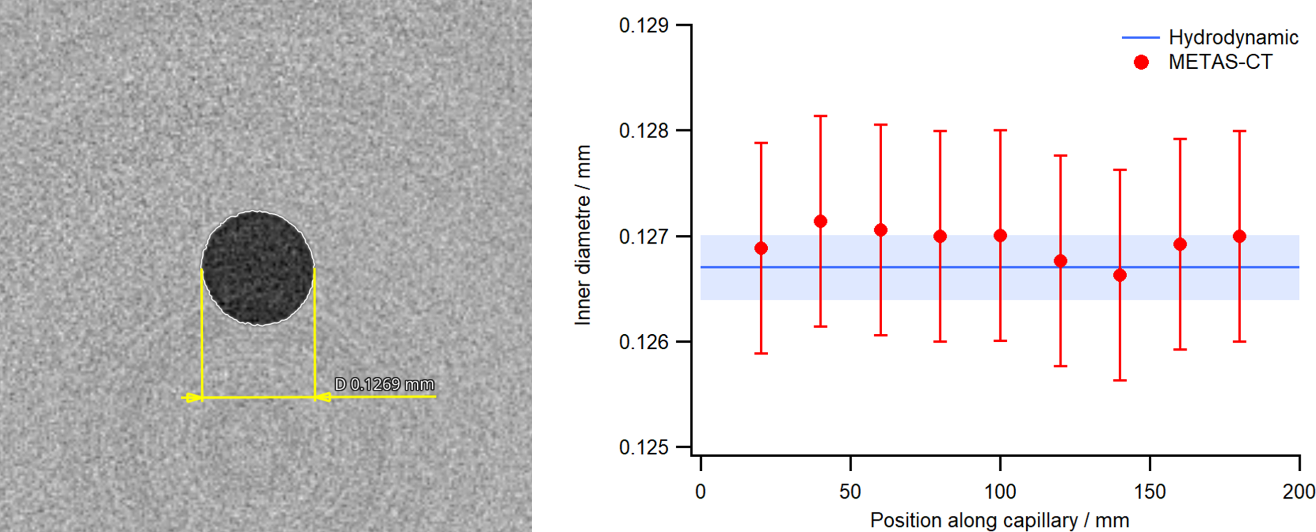
Use case 4: Micro-capillary
- Function: Flow resistance for viscosity measurements, nominal inner diameter 0.13 mm
- Material: Soda glass
- Outer dimensions: 200 x 4 x 4 mm3 (scanned in 9 positions along the capillary)
- Measurement uncertainty estimation: hybrid [4]
- Measurand: Inner diameter
XCT slice of the glass micro capillary (L = 200 mm).Comparison of the measured hydrodynamic diameter compared to diameters determined by XCT at different positions along the capillary. XCT measurement uncertainty was dominated by the surface determination, distorted by beam hardening, and estimated at 1 µm.
References
[1] Küng A, Meli F and Thalmann R 2007 Ultraprecision micro-CMM using a low force 3D touch probe Meas. Sci. Technol. 18 319–27
[2] Lüthi M, Bircher B A, Meli F, Küng A and Thalmann R 2020 X-ray flat-panel detector geometry correction to improve dimensional computed tomography measurements Meas. Sci. Technol. 31 035002
[3] Bircher B A, Neuhaus S, Küng A and Meli F 2021 Measurement of temperature induced X-ray tube transmission target displacements for dimensional computed tomography Precis. Eng. 72 409–16
[4] Bircher B A, Meli F, Küng A and Thalmann R 2020 METAS-CT: Metrological X-ray computed tomography at sub-micrometre precision euspen’s 20th International Conference & Exhibition (Geneva, Switzerland (virtual))
[5] Bircher B A, Meli F, Küng A and Thalmann R 2018 A geometry measurement system for a dimensional cone-beam CT 8th Conference on Industrial Computed Tomography, Wels, Austria (iCT 2018)
[6] Binder F et al. 2021 Methodology to determine model parameters for virtual CTs (to be submitted)